Composite Structural Systems
In steel and concrete composite construction, the two materials are integrated in structural members to combine their advantages. The excellent structural characteristics of composite members, including high strength, stiffness, and ductility, make them an appealing option for many building configurations. My work has focused on documenting composite member and frame behavior and addressing key design issues through targeted studies utilizing advanced computational formulations and detailed examination of experimental results.
Mixed Beam Finite Element Formulation
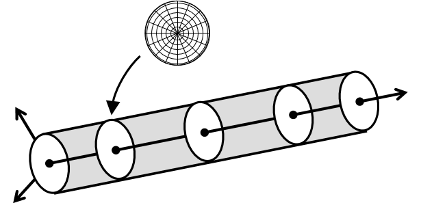
A key component of this work was the development of a distributed plasticity finite element formulation for composite beam-columns. The finite element is suitable for nonlinear static and dynamic analyses of complete composite structural systems and was implemented in the OpenSees framework. Two- and three-dimensional mixed beam elements form the cornerstone of the model. A mixed basis for the formulation was chosen to allow for accurate modeling of both material and geometric nonlinearities. New uniaxial constitutive relations for the concrete and steel elements simulate the cyclic response of concrete-filled steel tube and steel reinforced concrete members. The relations account for the salient features of each material as well as the interaction between the two, including for concrete: varying levels of confinement within a section, cracking, crushing, and spalling, and for steel: cyclic plasticity, residual stresses, and local buckling. Models for wide flange steel beams, wide flange or rectangular hollow structural steel braces, and connection regions were also developed to allow for the analysis of complete composite frames. Validation was conducted against a comprehensive set of experimental results from monotonically and cyclically loaded specimens, confirming the capability of the formulation to accurately produce realistic simulations of element and frame behavior.
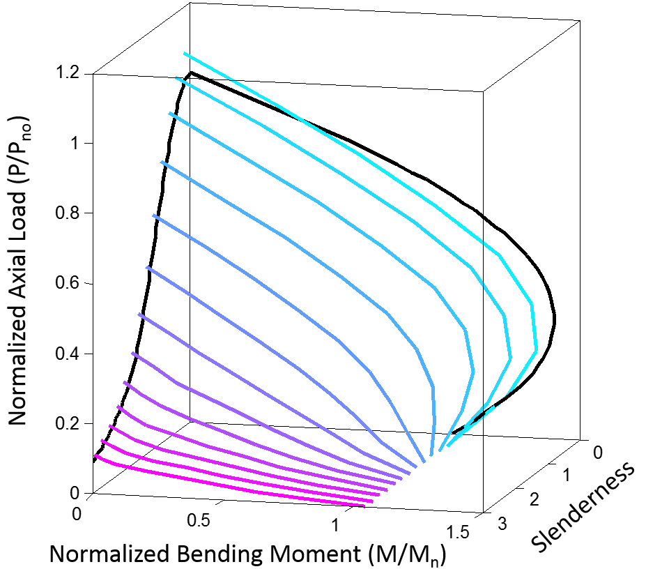
Full-Scale Slender Concrete-Filled Beam-Column Tests
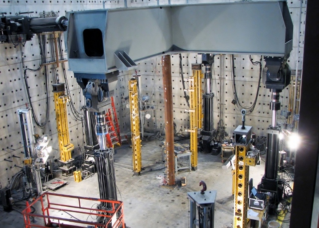
Project collaborators conducted a series of experiments on full-scale slender concrete-filled steel tubes beam-columns. Eighteen specimens were tested with variations in steel tube shape and size, length, and concrete strength. The tests explored several aspects of the behavior of composite columns, including the multi-dimensional interaction surface, biaxial cyclic seismic behavior, and evolution of damage. The specimens were extensively instrumented with redundant measuring systems to assess and quantify the overall behavior of the composite members. A complex loading protocol was used in the experimental program, including monotonic and cyclic loading that allowed detailed evaluation of the complete beam-column response. The experimental data provided a challenging validation for the finite element formulation. Also, a detailed identification of the many stability limit points which occurred during each test provided valuable data in the assessment of stability design provisions and the cyclic evolution of beam-column interaction strength.
Stability Analysis and Design
The direct analysis method defined within the AISC Specification for Structural Steel Buildings provides a straightforward and accurate way of addressing in-plane stability considerations of frames. In this method, required strengths are determined with a second-order elastic analysis where members are modeled with a reduced rigidity and initial imperfections are either directly modeled or represented with notional lateral loads. The method allows for the computation of available strength based on the unsupported length of the column, eliminating the need to compute an effective length factor. The validity of this approach has been established for structural steel frames through comparisons between fully nonlinear analyses and elastic analyses. The comparable method for design by second-order elastic analysis defined in the ACI Building Code Requirements for Structural Concrete was similarly validated for reinforced concrete frames. In this work, a suitable reduced rigidity was calibrated and the direct analysis method in general was validated for steel-concrete composite frames. The results of this study form the basis for the new design provisions on the required stiffness for the calculation of required strength of composite columns in the 2016 AISC Specification for Structural Steel Buildings.
Seismic Behavior
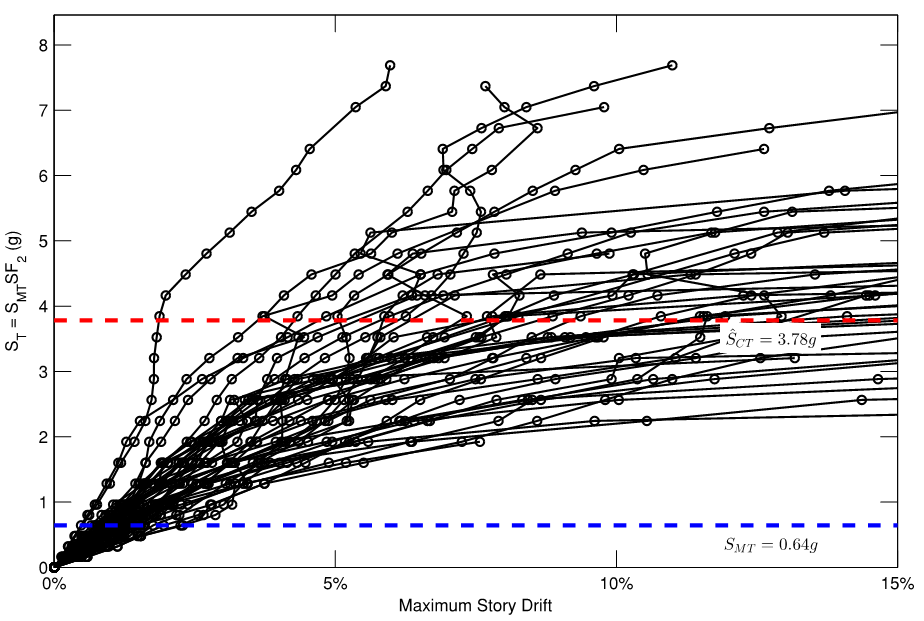
A key component of seismic design in the United States is the allowance for inelasticity in structural elements subjected to severe earthquake ground motions. However, static elastic analysis is prevalent for seismic design in current practice. Because of this, seismic performance factors have been developed. The factors are: the response modification factor used in reducing seismic forces as determined through elastic methods; the displacement amplification factor used in amplifying displacements as determined through elastic methods; and the system overstrength factor used to estimate the actual strength as compared the to the design strength. These three factors are tabulated for a variety of seismic force resisting systems in national codes, however, they have been somewhat arbitrarily assigned. Many R factors were based largely on judgment and qualitative comparisons to the relatively few seismic force resisting systems that had known response capabilities. This is particularly true for composite frames where the seismic performance factors were assigned based on comparisons to similar structural steel and reinforced concrete systems. Through a series of nonlinear static pushover analyses and dynamic response history analyses on a suite of composite frames designed using current specifications the behavior of such frames was documented. Then, following the methodology described in FEMA P695 Quantification of Building Seismic Performance Factors rational seismic performance factors for composite moment frames and braced frames were developed.
Bond Strength
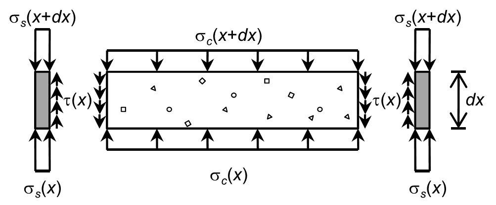
To ensure that the beneficial effects of the interaction between the steel and concrete within a composite frame are realized, it is important to have a comprehensive understanding of the material interface, particularly in critical connection regions where load is transferred to the column from girders or braces. For concrete-filled steel tubes, transfer of stress through natural bond, without the use of steel stud anchors or bearing mechanism, is often the most economical connection detail; however, efforts to characterize the bond strength are hindered by varying experimental results, even among similar specimens. The natural bond behavior of concrete-filled steel tubes was examined in this work, synthesizing past experimental research, developing a new formula for nominal bond strength, and investigating the distribution of slip and bond stress along the length of the column. This work formed the basis for the new design provisions for natural bond strength in the 2016 AISC Specification for Structural Steel Buildings.
Links:
- Composite Systems Wiki (based on the CFT Synopsis)
- Prof. Hajjar's Composite Website
- Steel-Concrete Composite Column Database
- Concrete-Filled Steel Tube (CFT) Load Transfer Database
Ponding
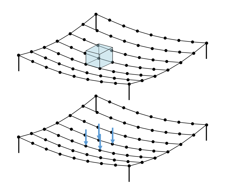
The accumulation of water on roofs can cause progressively increasing deformations and even collapse. Water gravitates to low points in a roof, resulting in nonuniform loading that is dependent on the deflected shape of the roof. This effect, known as ponding, is a design consideration for all buildings. The most commonly used method of assessing roofs for ponding was developed over 50 years ago and has many limitations. In this work, I developed a new method of design, the direct analysis method for ponding, which more accurately captures the behavior of roofs under ponding conditions through nonlinear analysis. The new method provides more accurate solutions and is applicable to a wider range of cases while still being simple to use for practicing engineers.
Links:
Steel Bolted Connections
Bearing and Tearout of Steel Bolted Connections
The determination of the strength of a bolt group is complicated by the fact that any one of several limit states can control the effective strength of an individual fastener. There is uncertainty in how to properly combine individual strengths to obtain the strength of the bolt group as a whole. This is particularly true for eccentrically loaded connections were the direction of loading on each bolt is different and difficult to determine. If cases where the limit state of tearout did not need to be checked could be identified and codified, the design of these connections would be much simpler and thus a more attractive option. In the first phase of this research, a database will be compiled with all available and relevant published experimental studies on bolted connections. The data will then be examined to determine if adjustments to the AISC Specification can be justified. In the second phase, new physical experiments will be performed on bolted connections to fill gaps in the database and contribute to the justification for potential changes to the AISC Specification.
Behavior of Bolted Steel Slip-critical Connections with Fillers
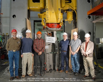
Filler plates are used in bolted steel connections where hot-rolled structural steel members of different depths are joined. Filler plates are commonly found in long-span truss connections, steel girders splices, and column splices. Typical filler plate thicknesses range from 6 mm to 102 mm (1/4 in. to 4 in.) or larger. For long-span trusses in particular, recent fabrication and erection practices have favored the use of oversized holes in connections with fillers so that the trusses may be erected in place without first checking fit-up through a trial erection on the ground. Sixteen specimens were tested in Talbot Laboratory at the University of Illinois at Urbana-Champaign in a 13.3 MN (3,000 kip) testing machine. The specimens were intended to replicate common bolted splice connections between wide-flange members of different depths, designed to explore the effect of filler thickness, filler development, development method, and bolt pretension method.
Links:
- Papers published in the Journal of Constructional Steel Research (I. Performance and II. Behavior)
- Newmark Structural Laboratory Report